
The Complete MRCOOL DIY® Mini-Split Technical Installation Guide
Master a professional-quality install with this in-depth HVAC guide to the MRCOOL DIY® ductless mini-split heat pump — covering components, placement, electrical, pre-charged line set connections, startup testing, and pro tips for peak performance.
Size Your Room (BTU Calculator) Watch the Install Video Build Your MRCOOL System
Transform Your Home Comfort with MRCOOL DIY®
The MRCOOL DIY® Mini-Split System delivers energy-efficient heating and cooling with true do-it-yourself installation. Thanks to factory pre-charged Quick Connect® line sets and an inverter-driven compressor, homeowners can achieve reliable, quiet comfort without vacuum pumps, gauges, or refrigerant handling.
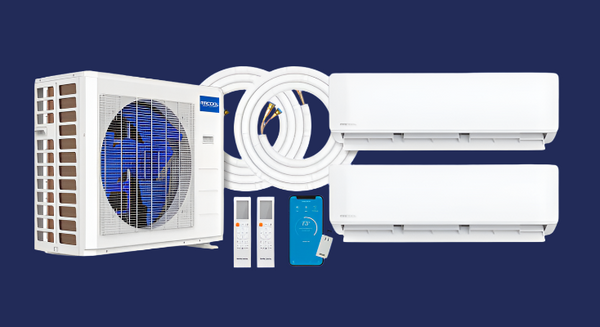
System Components & How They Work
- Outdoor Condenser (Heat Pump): Variable-speed inverter compressor, condenser coil, fan motor, control PCB; pre-charged with R-454B (Gen 5), Gold Fin® coating, Quick Connect® service valves.
- Indoor Air Handler (Evaporator): Cross-flow blower, evaporator coil, EEV (electronic expansion valve), auto-swing louvers, onboard sensors, Wi-Fi control (Smart HVAC App).
- Pre-Charged Line Set: Sealed, pre-charged copper lines with flare fittings; typical lengths 16′/25′/35′/50′; includes DIYPRO® armored cable for power/communication.
- Condensate Drain: Gravity drain from indoor unit to exterior (avoid traps/sags; maintain continuous downward slope).
Long-tail keywords: MRCOOL pre-charged line set, Quick Connect mini split installation, inverter heat pump ductless AC, R-454B low-GWP refrigerant, DIY mini split wiring diagram.
Pre-Installation Planning & Code Notes
- Verify circuit/breaker sizing (208/230V, 1-phase; see unit MCA/Max Fuse).
- Confirm line set length and maximum vertical lift for your model.
- Plan drain outlet and wall penetration (3.5″ hole with downward pitch).
- Check clearance: indoor 6″ from ceiling; outdoor 24″ rear/12″ sides/60″ above.
- Snow/wind exposure: elevate condenser 12–18″ in snow zones; avoid prevailing wind into coil.
Pro Tip: Print the wiring diagram on the condenser access panel and keep it nearby during terminations.
Selecting Indoor & Outdoor Locations
Indoor Air Handler
- Use an exterior wall for shortest run; center for balanced airflow.
- Avoid direct sun, door drafts, curtains, or shelves within 40″.
- Maintain continuous downward slope on the drain hose.
Outdoor Condenser
- Level concrete pad or rated wall bracket with anti-vibration pads.
- Keep coil area clear of shrubs/debris; no recirculating exhaust into walls or fences.
- Maintain service access for gauges/electrical (even if not used at install).
Mount the Indoor Unit
- Bracket: Fasten to studs; verify level (prevents condensate overflow).
- Wall Penetration: Drill ~3.5″ hole with 5° downward pitch; insert wall sleeve.
- Bundle & Feed: Tape suction/liquid lines + drain + cable; gently feed outdoors.
- Hang: Seat the unit on the bracket; confirm rigid, rattle-free mount.
Pro Tip: Protect flare threads; don’t kink the suction line — a flattened bend raises superheat and tanks capacity.
Set the Outdoor Condenser
- Place & Level: Pad or bracket; ensure water sheds away from base.
-
Connect Line Set: Clean flares; hand-start threads; torque to spec:
- ¼″ (liquid): ~33–38 ft-lb
- ⅜″ (some 18k): ~45–50 ft-lb
- ½″ (suction on larger units): ~50–55 ft-lb
- Open Valves: Back-seat (fully CCW) liquid then suction service valves to release charge.
Pro Tip: A drop of POE oil on flare threads reduces galling; never use thread sealant on flare seats.
Electrical Connections (Follow Your Model Diagram)
- Install disconnect and dedicated breaker per nameplate MCA/Max Fuse.
- Run the DIYPRO® armored cable between indoor/outdoor; match terminals 1-2-3 (L1/L2/Signal) color-for-color.
- Bond ground at both units; use copper conductors; tighten to listed torque.
- Dress conductors to avoid fan contact; close all covers for rain rating.
Long-tail anchors: DIY mini split wiring diagram 230V, MRCOOL 18k breaker size, how to wire Quick Connect mini split, NEC outdoor disconnect requirements.
Weatherproofing, Drain & Line Set Finish
- Seal wall sleeve with silicone or non-hardening putty (air/water barrier).
- Install LineGuard® or line-hide channel for UV protection and clean aesthetics.
- Test drain by pouring water into pan; confirm steady exterior discharge.
- Wrap exposed fittings with closed-cell insulation to prevent sweating.
Startup, Testing & Commissioning
- Energize: Turn on breaker; allow control board to boot (~60–120s).
- Functional Test: Run Cool, Heat, and Fan; verify mode changes and outdoor fan/compressor response.
- Temperature Split: Measure ΔT supply-to-return (target ~18–22°F in cool, normal humidity).
- Leak Check: Use bubble solution at flare joints and valve stems; re-torque if needed.
- App Setup: Pair with the MRCOOL Smart HVAC App; set schedules, geofencing, and Follow Me® temperature.
Pro Tip: If performance seems low, check fan speed, filter cleanliness, and that the drain isn’t siphoning conditioned air (seal sleeve!).
Performance Optimization & Maintenance
- Filters: Clean every 30–60 days; replace as needed.
- Coils: Use the MRCOOL Care Kit every 6 months to clean evaporator and condenser coils.
- Electrical: Re-torque terminals annually; inspect for heat discoloration.
- Insulation: Replace damaged suction insulation to maintain capacity and prevent condensation.
- Winter: Keep snow/ice clear; consider wind baffle in high-wind zones.
Technical Specifications (Example — 18K Single-Zone)
| Parameter | Specification |
|---|---|
| Cooling Capacity | 18,000 BTU/h |
| Heating Capacity | ~20,000 BTU/h |
| SEER2 / EER | ~22.0 / ~12.5 |
| HSPF2 (Region 4 / 5) | ~10.5 / ~8.5 |
| Power Supply | 208/230V, 1Ph, 60Hz |
| MCA / Max Fuse | 15A / 20A (model-dependent) |
| Refrigerant | R-454B (factory charge in sealed lines) |
| Line Set Length | 25′ standard (16′–50′ options) |
| Max Vertical Lift | ~25′ (see model data) |
| Operating Range | Cool 5–122°F / Heat 5–75°F (approx.) |
| Sound Level | Indoor 24–39 dB(A) / Outdoor ~51 dB(A) |
Values may vary by generation/model. Consult the exact P-tag/engineering data sheet for final ratings and electrical requirements.
Tech FAQs
Do I need to pull a vacuum on a MRCOOL DIY® system?
What if my run is longer than the included line set?
Which breaker size should I use?
Ready to Build Your System?
Shop MRCOOL DIY® Systems Calculate Your BTU Step-by-Step Install Video
Shop MRCOOL 5th Gen Single-Zone by BTU Size
- MRCOOL 9k BTU single-zone DIY mini split for small bedrooms and offices
- MRCOOL 12k BTU DIY mini split for medium-size rooms with efficient cooling
- MRCOOL 18k BTU single-zone mini split with R-454B for large rooms
- MRCOOL 24k BTU DIY mini split for garages, bonus rooms, and open areas
- MRCOOL 36k BTU single-zone mini split for extra-large spaces or workshops
Not sure which size you need? Try the MRCOOL BTU calculator to find the perfect system size.